The problem with Phong, with regard to the reflection and view directions being greater than 90 degrees, can be solved by changing the computation. This modified model is called the Blinn-Phong specular model or just the Blinn specular model.
It is no more physically correct than the Phong model. But it does tend to account for more than Phong.
The main problem with Phong is that the angle between the view direction and the reflection direction has to be less than 90 degrees in order for the specular term to be non-zero.

The angle between V and R is greater than 90 degrees. Cases like this are not modeled correctly by Phong. There could be microfacets at the point which are oriented towards the camera, but Phong cannot properly model this. The problem is that the dot product between the view direction and reflection direction can be negative, which does not lead to a reasonable result when passed through the rest of the equation.
The Blinn model uses a different set of vectors for its computations, one that are less than 90 degrees in all valid cases. The Blinn model requires computing the half-angle vector. The half-angle vector is the direction halfway between the view direction and the light position.


When the view direction is perfectly aligned with the reflected direction, the half-angle vector is perfectly aligned with the surface normal. Or to put it another way, the half-angle is the direction the surface normal would need to be facing in order for the viewer to see a specular reflection from the light source.

So instead of comparing the reflection vector to the view direction, the Blinn model compares the half-angle vector to the surface normal. It then raises this value to a power representing the shininess of the surface.

The angle between the half-angle vector and the normal is always less than 90 degrees. So the Blinn specular model produces similar results to the Phong model, but without some of Phong's problems. This is demonstrated in the Blinn vs Phong Lighting tutorial.
The controls are similar to the last tutorial. Pressing the H key will switch between Blinn and Phong specular. Pressing Shift+H will switch between diffuse+specular and specular only. Because the specular exponents have different meanings between the two lighting models, each model has a separate exponent. The keys for changing the exponent values will only change the value for the lighting model currently being viewed.
The real work here is, as before, in the shader computations. Here is the main code for computing the diffuse + Blinn illumination.
Example 11.2. Blinn-Phong Lighting Shader
vec3 lightDir = vec3(0.0);
float atten = CalcAttenuation(cameraSpacePosition, lightDir);
vec4 attenIntensity = atten * lightIntensity;

vec3 surfaceNormal = normalize(vertexNormal);
float cosAngIncidence = dot(surfaceNormal, lightDir);
cosAngIncidence = clamp(cosAngIncidence, 0, 1);

vec3 viewDirection = normalize(-cameraSpacePosition);

vec3 halfAngle = normalize(lightDir + viewDirection);
float blinnTerm = dot(surfaceNormal, halfAngle);
blinnTerm = clamp(blinnTerm, 0, 1);
blinnTerm = cosAngIncidence != 0.0 ? blinnTerm : 0.0;
blinnTerm = pow(blinnTerm, shininessFactor);

outputColor = (diffuseColor * attenIntensity * cosAngIncidence) +
    (specularColor * attenIntensity * blinnTerm) +
    (diffuseColor * ambientIntensity);
The half-angle vector is computed by normalizing the sum of the light direction and view direction vectors. As before, we take the dot product between that and the surface normal, clamp, then raise the result to a power.
Blinn specular solves the Phong problem with the reflection direction.

The Blinn version is on the left, with the Phong version on the right.
The Blinn specular exponent does not mean quite the same thing as the Phong exponent. In general, to produce a highlight the same size as a Phong one, you will need a larger Blinn exponent. Play around with the different exponents, to get a feel for what Blinn and Phong can and cannot achieve.
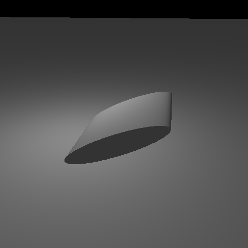
There are still a few artifacts in the rendering. For example, if you arrange the light, object, and camera as follows, you can see this:
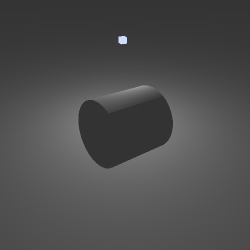
The cylinder looks like it has a very sharp corner. What causes this? It is caused by this line in the shader:
blinnTerm = cosAngIncidence != 0.0 ? blinnTerm : 0.0;
If the angle between the normal and the light direction is greater than 90 degrees, then we force the specular term to zero. The reason behind this is very simple: we assume our surface is a closed object. Given that assumption, if the normal at a location on the surface is facing away from the light, then this could only happen if there is some other part of the surface between itself and the light. Therefore, the surface cannot be directly illuminated by that light.
That is a reasonable assumption, and it certainly makes sense in reality. But real-life objects don't have these kinds of hard specular lines. So what are we missing in our model?
What we are missing is that point lights don't exist in the real world. Light illumination does not come from a single, infinitely small location in space. Even the size of the Sun relative to Earth has a significant area. So what this means is that, for a given point on a surface, it could be in partial view of the light source. Imagine Earth at sunset for an example: part of the sun is below the horizon and part of it is not.
Since only part of the light is visible from that point on the surface, then only part of the light contributes to the overall illumination. So at these places where you might get hard specular boundaries, under more real lighting conditions, you still get a semi-gentle fall-off.
That's all well and good, but modeling true area lights is difficult even for simple cases. A much simpler way to resolve this is to not use such a low specular exponent. This specular exponent is relatively small, leading to a very broad specular highlight. If we restrict our use of a specular term to surfaces who's specular exponent is reasonably large, we can prevent this artifact from appearing.
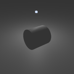
Here is the same scene, but with a larger exponent:
We could also adjust the specular reflectance, so that surfaces with a low specular exponent also have a small specular reflectance.