In this tutorial, we will investigate specific problems with regard to orienting objects.
Remember a few tutorials back, when we said that a rotation matrix is not a rotation matrix at all, that it is an orientation matrix? We also said that forgetting this can come back to bite you. Well, here's likely the most common way.
Normally, when dealing with orienting an object like a plane or spaceship in 3D space, you want to orient it based on 3 rotations about the 3 main axes. The obvious way to do this is with a series of 3 rotations. This means that the program stores 3 angles, and you generate a rotation matrix by creating 3 rotation matrices based on these angles and concatenating them. Indeed, the 3 angles often have special names, based on common flight terminology: yaw, pitch, and roll.
Pitch is the rotation that raises or lowers the front of the object. Yaw is the rotation that turns the object left and right. Roll is the rotation that spins it around the direction of motion. These terms neatly duck the question of what the axes technically are; they are defined in terms of semantic axes (front, left, direction of motion, etc), rather than a specific model space. So in one model space, roll might be a rotation about the X axis, but in another, it might be a rotation about the Z axis.
One of the first problems you will note is that the order you apply these rotations matter. As previously stated, a rotation matrix is an orientation transform. Each transform defines a new coordinate system, and the next transform is based on an object in the new space. For example, if we apply the roll first, we have now changed what the axis for the subsequent yaw is.
You can use any order that you like, so long as you understand what these angles mean. If you apply the roll first, your yaw and pitch must be in terms of the new roll coordinate system, and not the original coordinate system. That is, a change that is intended to only affect the roll of the final space may need yaw or pitch changes to allow it to have the same apparent orientation (except for the new roll, of course).
But there is a far more insidious problem lurking in here. And this problem happens anytime you compute a final rotation from a series of 3 rotations about axes perpendicular to each other.
The tutorial project Gimbal Lock illustrates this problem. Because the problem was first diagnosed with a physical device called a gimbal, the problem has become known as gimbal lock.
A gimbal is a pivoted support that provides the ability to rotate in one axis. A gimbal can be mounted within another gimbal. The Gimbal Lock project has a set of 3 square gimbals, each with a pivot axis that is perpendicular to the other two. This effectively mimics the common yaw/pitch/roll angle setup.
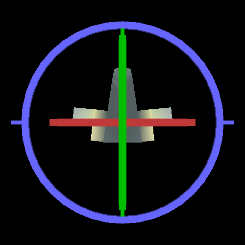
You can control the orientation of each gimbal separately. The W and S keys control the outer gimbal, the A and D keys control the middle gimbal, and the Q and E keys control the inner gimbal. If you just want to see (and affect) the orientation of the ship, press the SpaceBar to toggle drawing the gimbal rings.
The first thing you discover when attempting to use the gimbals to orient the ship is that the yaw, pitch, and roll controls of the gimbal change each time you move one of them. That is, when the gimbal arrangement is in the original position, the outer gimbal controls the pitch. But if you move the middle gimbal, it no longer controls only the pitch. Orienting the ship is very unintuitive.
The bigger is what happens when two of the gimbals are parallel with one another:
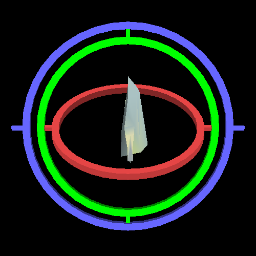
Recall that the purpose of the three gimbals is to be able to adjust one of the three angles and orient the object in a particular direction. In a flight-simulation game, the player would have controls that would change their yaw, pitch, and roll. However, look at this picture.
Given the controls of these gimbals, can you cause the object to pitch up and down? That is, move its nose up and down from where it is currently? Only slightly; you can use the middle gimbal, which has a bit of pitch rotation. But that is not much.
The reason we do not have as much freedom to orient the object is because the outer and inner gimbals are now rotating about the same axis. This means you really only have two gimbals to manipulate in order to orient the red gimbal. And 3D orientation cannot be fully controlled with only 2 axial rotations, with only 2 gimbals.
When gimbals are in such a position, you have what is known as gimbal lock; you have locked one of the gimbals to another, and now both cause the same effect.
Before we find a solution to the problem, let's review the code. Most of it is nothing you have not seen elsewhere, so this will be quick.
There is no explicit camera matrix set up for this example; it is too simple for that. The three gimbals are loaded from mesh files as we saw in our last tutorial. They are built to fit into the above array. The ship is also from a mesh file.
The rendering function looks like this:
Example 8.1. Gimbal Lock Display Code
void display()
{
    glClearColor(0.0f, 0.0f, 0.0f, 0.0f);
    glClearDepth(1.0f);
    glClear(GL_COLOR_BUFFER_BIT | GL_DEPTH_BUFFER_BIT);

    glutil::MatrixStack currMatrix;
    currMatrix.Translate(glm::vec3(0.0f, 0.0f, -200.0f));
    currMatrix.RotateX(g_angles.fAngleX);
    DrawGimbal(currMatrix, GIMBAL_X_AXIS, glm::vec4(0.4f, 0.4f, 1.0f, 1.0f));
    currMatrix.RotateY(g_angles.fAngleY);
    DrawGimbal(currMatrix, GIMBAL_Y_AXIS, glm::vec4(0.0f, 1.0f, 0.0f, 1.0f));
    currMatrix.RotateZ(g_angles.fAngleZ);
    DrawGimbal(currMatrix, GIMBAL_Z_AXIS, glm::vec4(1.0f, 0.3f, 0.3f, 1.0f));

    glUseProgram(theProgram);
    currMatrix.Scale(3.0, 3.0, 3.0);
    currMatrix.RotateX(-90);
    //Set the base color for this object.
    glUniform4f(baseColorUnif, 1.0, 1.0, 1.0, 1.0);
    glUniformMatrix4fv(modelToCameraMatrixUnif, 1, GL_FALSE, glm::value_ptr(currMatrix.Top()));

    g_pObject->Render("tint");

    glUseProgram(0);

    glutSwapBuffers();
}
The translation done first acts as our camera matrix: positioning the objects far enough away to be comfortably visible. From there, the three gimbals are drawn, with their appropriate rotations. Since each rotation applies to the previous one, the final orientation is given to the last gimbal.
The DrawGimbal function does some rotations of its own, but
this is just to position the gimbals properly in the array. The gimbals are given a
color programmatically, which is the 3rd parameter to
DrawGimbal.
After building up the rotation matrix, we draw the ship. We use a scale to make it reasonably large, and then rotate it so that it points in the correct direction relative to the final gimbal. In model space, the ship faces the +Z axis, but the gimbal faces the +Y axis. So we needed a change of coordinate system.