The next step when working with textures is to associate a texture with locations on the surface of an object. But before we can do that, we need to have a discussion about what it means to interpolate a value across a triangle.
Thus far, we have more or less glossed over the details of interpolation. We expanded on this earlier when we explained why per-vertex lighting would not work for certain kinds of functions, as well as when explaining why normals do not interpolate well. But now that we want to associate vertices of a triangle with locations on a texture, we need to fully explain what interpolation means.
The main topic is linearity. In the earlier discussions, it was stressed that interpolation was linear. The question that was danced around is both simple and obscure: linear in what space?
The perspective projection is a non-linear transform; that's why a matrix multiplication is insufficient to express it. Matrices can only handle linear transformations, and the perspective projection needs a division, which is non-linear. We have seen the effect of this non-linear transformation before:

The transformation from normalized device coordinate space to window space is fully linear. So the problem is the transformation from camera space to NDC space, the perspective projection.
From this diagram we see that lines which are parallel in camera space are not necessarily parallel in NDC space; this is one of the features of non-linear transforms. But most important of all is the fact that the distance between objects has changed non-linearly. In camera-space, the lines parallel to the Z axis are all equally spaced. In NDC space, they are not.
Look at the lines A and B. Imagine that these are the only two vertices in the object. In camera-space, the point halfway between them is C. However, in NDC space, the point halfway between them is D. The points C and D are not that close to one another in either space.
So, what space has OpenGL been doing our interpolation in? It might seem obvious to say window space, since window space is the space that the rasterizer (the hardware that does the interpolating) sees and uses. But if it had, we would have had a great many interpolation problems.
Consider interpolating camera space positions. This only works if the interpolation happens in camera-space (or some linear transform thereof). Look at the diagram again; the camera-space position C would be computed for the NDC location D. That would be very wrong.
So our interpolation has somehow been happening in camera space, even though the rasterizer only sees window space. What mechanism causes this?
The ability to linearly interpolate values in pre-projection space is called perspective-correct interpolation. And we now get to the final reason why our vertex shader provides values in clip-space rather than having the shader perform the perspective divide. The W term of clip-space is vital for performing perspective-correct interpolation.
This makes sense; the clip-space W is after all what makes our transformation non-linear. Perspective-correction simply uses the clip-space W to adjust the interpolation so that it happens in a space that is linear with respect to clip-space. And since clip-space is a linear transform of camera space (using 4D homogeneous coordinates), everything works out. Technically, perspective-correct interpolation does not cause interpolation in camera space, but it interpolates in a space that is a linear transform from camera space.
To see the effects of perspective-correction most dramatically, fire up the Perspective Interpolation project.
There are no camera controls in this demo; the camera is fixed so as to allow the illusion presented to work. Pressing the P key switches between perspective-correct interpolation and window-space linear interpolation.
Figure 14.5. Perspective Correct Interpolation
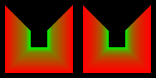
Left: Linear interpolation. Right: Perspective-correct interpolation
The interesting bit is as follows. Switch to the perspective-correct version (a message will appear in the console window) and press the S key. Now, the P key no longer seems to have any effect; we seem to be trapped in linear-interpolation.
What happens is that the S key switches meshes. The “fake” mesh is not really a hallway; it is perfectly flat. It is more or less a mesh who's vertex positions are in NDC-space, after multiplying the original hallway by the perspective matrix. The difference is that there is no W coordinate; it's just a flat object, an optical illusion. There is no perspective information for the perspective-correction logic to key on, so it looks just like window-space linear interpolation.
The switch used to turn on or off perspective-correct interpolation is the
interpolation qualifier. Previously, we said that there were three qualifiers:
flat, smooth, and
noperspective. The third one was previously left undefined
before; you can probably guess what it does now.
We are not going to use noperspective in the immediate future.
Indeed, doing window space interpolation with a perspective projection is exceedingly
rare, far more rare than flat. The important thing to understand from
this section is that interpolation style matters. And smooth will be
our default interpolation; fortunately, it is OpenGL's default too.